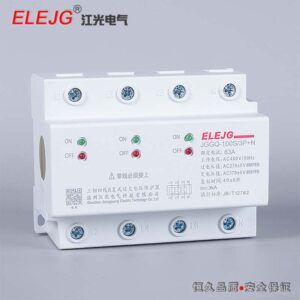


JGQ1 seriesDual power supplyAutomatic transfer switch(hereinafter referred to as the transfer switch) is suitable for AC 50Hz or 60Hz, rated working voltage 400V, below the double circuit power supply system. Selective conversion between the two power supplies can be made as required. The product has the functions of short circuit, overload, undervoltage and loss of voltage, and also has the functions of fire protection, double division and output closing signal.
It is especially suitable for the installation and use of lighting lines in office buildings, shopping malls, banks, stations, hospitals and high-rise buildings that require fire protection requirements.
The product conforms to GB/T14048, 11 standards.
3. Normal working conditions
3.1 The upper limit of the ambient air temperature shall not exceed +40°C, and the lower limit shall not exceed °C.
The average value of 24h does not exceed +35°C.
3.2 The altitude of the installation site shall not exceed 2000m.
3.3 The relative humidity of the atmosphere does not exceed 50% at the ambient air temperature +40°C, and at lower temperatures, there can be higher humidity; When the average monthly minimum temperature of the wettest month is +25°C, the average maximum relative humidity is 90%, taking into account the factors
Humidity changes occur on the surface of the product for condensation, special measures should be taken.
3.4 The pollution level is Class III.
3.5 There is no strong vibration and impact at the operation site, no corrosion and damage to the insulation harmful gases, no serious dust, no conductive particles and explosive dangerous substances,
No strong electromagnetic interference。
4. Product features
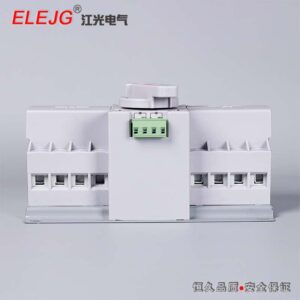
4.1 The structure is reasonable, the size is minimal, the appearance is beautiful, equipped with a protective cover, and the power supply is more safe and reliable.
4.2 The expansion function is complete, with short circuit, overload, phase loss, undervoltage and other protection.
4.3 With the EPS fire power interface, DC12~24V can be reliable and long-distance double division.
4.4 Noiseless operation, energy saving and consumption reduction, easy installation, simple operation, reliable and stable performance.
5. Product performance
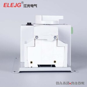
5.1 The transfer switch is composed of two miniature circuit breakers and motors and mechanical rotation devices combined into one and detects the two power supplies through the controller, when the circuit is abnormal, the controller makes a logical judgment on the detection results, according to the controller instructions
Drive the operating mechanism to open or close, so as to ensure the safe and reliable power supply to the load.
5.2 Switching and disconnection capabilities
5.3 Rated short-circuit breaking capacity: 3kA
5.4 Rated short-circuit turn-on capacity: 3kA
5.5 Conversion time: ≤3s
5.6 The control voltage of the transfer switch is AC230V
5.7 The mechanical life of the transfer switch (common and standby conversion) is 3000 times,
The electric life is 1500 times
5.8 Rated insulation voltage: U=500V
5.9 Rated working current: 10A, 16A, 20A, 25A, 32A, 40A, 63A.
5.10 In general, the transfer switch has the function of self-throwing and self-recovery, and the principle of priority of common power supply. If a special occasion requires a self-throwing non-resuming transfer switch, the user negotiates with the manufacturer to customize.
6. Operation and installation
If the circuit breaker is 3 poles, the neutral wire must be connected to the neutral terminal of the transfer switch (the commonly used neutral wire and the spare neutral wire in Figure 6.2 are connected to the 2# and 4# terminals respectively).
6.1 Main circuit wiring diagram
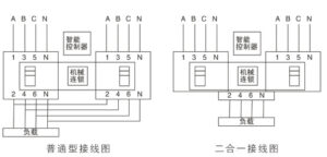
6.2 External power supply closing indication and fire power supply wiring diagram
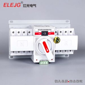
6.3 When the transfer switch needs to be operated manually, if it is JGQ1-63 type, the button switch should be in the manual position first, and then the handle can be rotated for common or standby conversion, if it is JGQ1-63 type, press the manual/automatic button, and when the manual indicator light is on, the common or standby conversion can be carried out. Put the control mode in the automatic position, and the transfer switch will enter the automatic working state; And the common power supply takes precedence.
6.4 When the transfer switch is connected to the line according to the wiring diagram, after the power is normally turned on, if the common power supply and the standby power supply are all normal, the indicator light (red) of the common power supply or standby power supply is lit, and the transfer switch works normally.